RB30 GTR – The Build
Here is a little taster of what’s to come! This is the car as it was delivered to me May 2008!
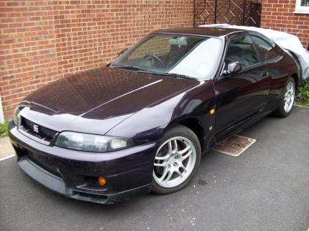
..And so it began! First job was of course going to be removal of the
 seized engine. I was in two minds which way to go with the rebuild so I thought I would see the damage before making a final decision. I was pretty sure looking in the engine bay it was not going to be a fun job. There is pipe work everywhere and the straight 6 lump was bound to weigh a fair bit. After a day or so of removing ancillaries and making sure I had removed all the pipework and wiring I was ready to lift it out. Getting the top bell housing bolts is one of the trickiest bits. I found the trick there was to unbolt the sub-frame and let the whole lot drop down a few inches to give you more space from above. Only just enough room though!
Strip Down and investigate
Once the engine was out I quickly begun stripping it down. Much to my annoyance I found this after removing the engine mounts and turbos from the side of the block.
 |
 |
A great big hole that shouldn’t be there! Not exactly what I had in mind! No wonder it was seized. The annoying thing was I had taken a good look around the block and under the car and there was no sign of this at all! Okay so now plans would have to change slightly but I still had two possible options, buy a
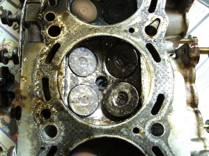
second-hand RB26 or do an RB30 conversion? But I would check the rest of the engine out first and do some research prior to deciding! Well I must say it didn’t get much better once I got inside the engine.. In fact it got worse! Not pretty at all!
 |
 |
 |
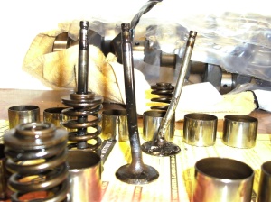
The head had taken a bit of a beating in the No2. chamber and consequently so had the valves and guides! Also where there was once a piston there was a complete void all bar the remnants of a mangled conrod! I Was going to need to strip it back to bare bones to find out what I could salvage if anything now. It really was the worse possible news!
 After fully stripping down the motor I found the remains of pistons in amongst the sump baffle and dow the oil lines and pretty much everywhere it shouldn’t have been! I was able to assess the actual damage. The cams had some nasty scoring and really were no good to reuse but the head other than the damaged valve guides and shrapnel wounds was in pretty good nick. After seeking a second opinion I decided it was definitely salvageable. After a few weeks of looking at secondhand RB26 motors and getting prices I finally decided I would go for the RB30 option. The challenge of building one was just too much to refuse! It took a while to find a source and get everything arranged but eventually I ordered 2 blocks in from Australia. 3 months or so later a large lorry arrived at the door with a battered crate in the back and two engine
 blocks hanging on for dear life! Thankfully all in tact though. Now if you are looking at doing this conversion you need to be careful which block you get as there are a couple of options on the RB30 depending on year and if it was a turbo car etc. I had researched all this very carefully and despite checking it all out with the supplier one of the blocks did not have the oil feed gallery required nor did it have a flat front face on the block which would later be needed to fit a belt tensioner. All was not lost though. These modifications could be made with a bit of extra work! As if I didn’t have enough to do already! There was a lot to take into account when doing the RB30 conversion with plenty of build threads to read and a handy guide to the RB30 conversion I set about putting it all into practice.
Preparing the RB30
Now I had settled on the route of my new project I had to decide what bits to go with the engine to make the most of it. I decided to be realistic seeing as it was my first complete build. So I decided to set a goal of 500-600bhp. Looking at all the info I had gleaned from numerous sources and talking to some helpful engine builders I decided I could and would run with the Stock RB30 bottom end.
 |
 |
 |
Both blocks I had sourced were in very good nick so I decided to sell the better one with the correct oil fittings and keep the hard work block for myself being that it would be harder to sell anyway. To get the block freshened up I would require all new bearings. I chose to go with  ACL Race bearings. I also purchased new Moly rings for the Std RB30 pistons. Before I got to carried away with shiny clean bits though the block was stripped and honed I then sent it off to be skimmed, after this there was a modification I needed to do to the block for mounting the top tensioner so I popped to my local machine shop, set the block up on a mill and carefully drilled and tapped the new hole position. Finally all the components to be reused were sent for cleaning in a chemical dip. I had tried to get as much of the block machining/modification done prior to it being cleaned so that once it was I did not have to worry about metal swarf going into oil gallerys and ruining bearings! Here are a few pictures showing the stages up to now.
 |
 |
 |
First Job now was to get the block painted so it didn’t go rusty after such a thorough clean! I quite like the raw colour it was so  chose to mix a hammerite based colour to match as best as I could! At this point the block also made it to the engine stand which was incentive in itself to get building! There were a couple of task to do prior to getting bits in the block though. Firstly I need to get the crank checked and polished and also fit an RB26 crank collar to drive the N1 oil that was going to be fitted. The RB30 has a narrow drive gear and this wears and can result in oil pump failure so it is a must as te upgrades go and not really that costly to do. Me being me decided I was not going to line someone elses pocket for a what looked like a relatively simple component to make so I managed to find myself a crank grind drawing for fitting the RB26 collars, working back from there and taking measurements from the crank and oil pump I came up with a nicely toleranced collar. I then did my own CAD drawings for both the collar and crank grinding and sent them off to my top class machinist. Next day I have the crank and collar ready to fit
 |
 |
 |
Fitting the Collar was one of the least fun jobs I have had to do for a while! It involves cooling the crank in a freezer ideally and heating the collar in the oven as the collar is designed such to be a tight interference fit. This is the kind of job you get one shot only at! Lucky for me my calculations for expansion worked out okay and the collar slipped on perfectly. As a precaution as with other collars out there I chose to put a couple of additional retaining grub screws through to collar and into the nose of the crank to make double sure it would never move!
 The crank could now be put to one side ready to go. Next job was to get the pistons and rods ready. I was going to run all standard bottom end internals but to try and give the rods a bit more strength and improve the balance I decided to lighten and balance the rods and then get them shot peened. I did not go crazy removing metal mainly just the casting marks and sharp edges All the rods
  and caps were weighed separately ending up with each total assembly having less that 1 gram difference. I also carried out the same process on the pistons but purely removing minimal metal to even out the weights. Finally the pistons and rods were assembled together and put to the side ready for assembly.At this point there was one last job I could think needed doing before I could start putting the block together. I needed a 4WD sump adapter and also that required some minor modifications to the block. Keeping with tradition no way I was buying one! I am very lucky to have an engineering background and access to some top class equipment and F1 machine shops so I would put all these to use in this instance. First of all I needed the shape for the plate. Rather than bodge a template trial and error style
  I borrowed an RB26 block from friend which has all the hole positions you require. I then used a 3D scanner to take all the critical points and surface positions I needed. Once I had this a couple of evenings on the computer and I have a 3D model of my sump plate. Taking some advice from my machinist we settled on some high grade aluminium plate to manufacture the adapter from and a few days later my machined part arrived. To complete the plate itself I added an alochrom finish to protect it from the elements and leave a clean semi prepped surface for the silicone gasket to later adhere to. The adapter plates have been requested by a number of people already and a kit can be supplied to order. Please see the sale section for information and pricing.
Block Modifications
 Now there were just a few small jobs to do before beginning assembly of the bottom end of the engine. If you read through the general build info for the RB30 you will find it is recommended to put oil restrictors in the block to control the oil flow to the head. Without this there is a possibility on a high output build at higher rpm most of the oil will end up in the head and not the sump ultimately leading to oil starvation and engine failure. although I was planning on limiting rpm to around 7000rpm max I thought I would build in this modification rather than take any chances. Another recommended modification which I did not do are to drill out the oil returns in the RB26 head to a large size to help the oil drain back faster to the sump. It is also thought that putting an additional return
  pipe from the head to the sump is beneficial. We will come to that a little later. last modifications to the block which would require drilling and a bit of grinding so better to do before you build it are tapping in a turbo oil drain help if you block doesn’t have one and also trimming the bolt head clearances for the sump adapter plate. Trimming the clearances was pretty simple, you just need to take care not to go too far. From the 3D CAD data I had used to create the sump plate I made
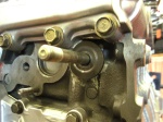
  some trimming templates from the block using paper which I then positioned using existing holes and spray mounted it in place so I could grind away accordingly. Another mod which I did not find out about until too late was the flat position on the front face of the block for the cam belt idle pulley. As with other RB30 features some blocks will have this and others will not. I believe you can get an off the shelf machined washer to resolve this problem but I overcame this myself by shaping a washer to fit over the lump on the block face. I bonded this in place with chemical metal and then made and piloted facing tool to machine it off ensuring the idle would sit square to the other pullies and not result in the belt riding off it.
 |
 |
 |
Head Repairs and Rebuild
Before I got carried away building the bottom end I decided to have a good look at the head and make sure I could salvage it in case I would have difficulty sourcing one. I could also use the empty block to rest the head when it came to sizing the shims and checking the cam fit. I managed to get hold of another scrap head with good valve guides to repair mine so I went about removal of guides from both heads.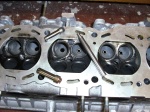 I did this by heating the cylinder heads up with a space heater and then pressing the guides out using a stepped pin I had turned up. The broken ones were quite tricky to get out as the pin would not rest square against the shattered end. persistence won out in the end though and after a few hours I had a functional set of guides. To check these had gone in square I took the valves and gave them a very quick lap in. After a quick whiz around you could see a nice solid grey around the valve
  seats. Sorted! I completed lapping all the valves in freshly before assembly. Time to assemble the springs into the head and. Quite a fiddly job. Trying to get the collets onto the end of the valve down inside the spring clamp which is down inside the spring recess in the head. A tip I learned in the past for this was apply a bit of grease or petroleum jelly to the grooves in the end of the valve. This way you can drop the collet into place and use a screw drive to stick it in place on the grease before releasing the clamp very carefully making sure not to disturb the resting collet!
  Once you get the knack of it it’s quite easy. Just quite a slow process. Now the valves were finally in place I was ready to begin the very painful process of shimming the head. The RB26 has solid cam followers. each of these are spaced with a steel shim to give the correct valve clearance. I had been very careful to number everything when taking the head apart so I could get it all back in the same place and hopefully avoid this job but as I had replaced the Stock cams with some HKS ones I was not going to get out of it! I started by noting the shim size currently in each valve. I then put the cams into position and
  bolted the caps down. Taking measurements of valve clearance from each valve in turn and then putting this into my shim chart I then could work out what shim size each valve required to run the correct clearance. With the set I had I managed to do just over half the cylinder head by swapping them around. I then when on a beg steel and borrow mission and my local skyline specialist loaned me a bucket of shims! After a lot of rooting around and a bit of DIY surface grinding I had completed the shim set.
Engine Block Assembly
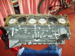
I could now start building the block up! First in place would be the new ACL race bearings to nestle the newly polished crank, the girdle then locked this all in place and was quickly followed by the pistons and rods and then the N1 oil and water pumps.
 |
 |
 |
The piston fitting was a slighty nerve-racking job being very carefully tapping them into the bore so as not to damage one of the new rings! The bottom end took shape very quickly once I was rolling. The adapter plate was next on and fitted up  perfectly due to the design process from the dummy block. At the various stages I checked everything was rotating freely. With the block near complete I could now finish off the assembly of the cylinder head and bolt it in place. Now with the bulk of the bottom end done I could bolt the head on and get this completed. The head was first bolted onto the block using the new high tensile head bolts. Once the head was secured to the block I made sure the pistons were in a position that could not collide with any valves and went about putting the cams in very carefully! After torquing the cam caps down I gave the cams a little turn to make sure they rotated freely and then put the backing plates on and pullies so I could align the timing marks for the cam and then the crank and fit the timing belt to prevent unwanted collision with valves and pistons! Getting all this done was a very satisfying step of progress and with it all belted up a quick rotational check and I was pleased as punch!
 |
 |
 |
Oil Pickup Pipe Manufacture
Now the engine was really taking shape! So where to now. It was time for a bit of fabrication I had not been looking for! Oil pickup pipe! With the RB30 block the pickup fixing point is halfway along the block as a pose to the RB26 which is at the towards the front of the block. This requires you to make a new pickup pipe to suit. Sounds easy enough and I guess it really was not that bad a job i the end but there are a few things you need to be aware of. Firstly with the 4WD sump the shaft through the sump goes almost exactly over the hole where the pickup fixes to the block. Also the space that you have to run the pickup along before you can direct it down to the sump well is quite narrow. In my wisdom I had decided to make my own sump plate form 8mm thick plate to push the limit a bit! Normally this would be 10mm.I can see now there is a good reason for that. It helps give you extra room! And trust me 2mm is a lot of space in this instance! Before I could get carried  away welding my pipe I had to check fit the sump. Straight away I hit a problem! The drive shaft outer through the sump fouled on the crank girdle! Possibly the extra 2mm would have meant this did not happen I am not sure. I did note the RB26 girdle has a little scollop in though so I took minimal material from the girdle to allow it to clear. I checked clearance by putting a small piece of blue tack on the girdle and lower the sump on. When it contacted the blue tack it would leave an imprint so I could see exactly when it was clearing. Now it was time to get the welder out! I decided I
  should be able to make one god pickup by using the stock RB30 and RB26 pick-ups to minimise forming tube to suit from complete scratch. Clearly the most important thing here is making sure the pickup is in the right place so it draws oil properly! If you are doing a sump extension this is no problem as you can cut a hole in your sump to see what you are working with. As I had no plans to do an extension I was working blind! Another option I considered was an external pickup. But in the end I was confident I had come up with an accurate way to jig the conventional pipe. The RB26 block has a blank
 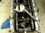 pickup position in the same place as the RB30. So what I would do was jig the oil pickup on the scrap block. First thing to do was cut the bracket off the RB26 pickup and bolt it to the scrap block. I then welded some braces to the pickup that were bolted to the block through some of the sump fixing points. I had to be careful here that there was no pre-tension on the braces before I welded them as this could pull the pipe out of place when I released the bolts holding it to the block. Once I was satisfied the braces where rigid and accurate I released the bolts holding the pickup pipe to the block. As planned it all stayed nicely in place and did not ping off anywhere!
  The next step was offer this up to the RB30 block and choose where I was going to cut it! I decided as good a place as any was just after the first bend in the pipe as I was going to need a new tight bend here to get from A-B! I cut the fixing flange from the pickup pipe and using the bit of pipe I had removed created a new tight bender. I simply did this with a blow torch, bench vice and pair of sockets that nicely fitted inside the pickup pipe. Reason for this was to try and prevent the pipe crushing in the bend as much as possible. With a bit of tweaking a bit at a
 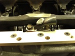 time I soon had a nice 90deg bend. The other point I should make at this point is when you have your flange loose you need to slot the bolt hole on one side as when you weld the 90deg bend over it you cannot put the bolt in from above because the pipe is in the way so you have to put the bolt in the block first and slide the pickup into place! At this point I check the sump clearance again on the RB30 block using the same blue tack method as before. There was plenty of room so no worries! Now I needed to connect the two ends. after offering up the RB30 pickup to see which area of tubing would best fill
  the gap I had I cut the flange and bend off the pipe and removed the filter mesh bits so I had as much pipe to start with as possible. That would turn out to be pretty much just enough! I cleaned the pipe up so it was a nice clean section of bend and then began tweaking it and trimming to suit. As I did not want weld spatter in my nice shiny block I jigged the end back in place on the old block. I was careful to remember to space the pickup end up by 8mm to allow for the difference of the sump well with the sump adapter plate fitted on the RB30. I double checked that everything looked like it all lined up the
  same as it had on the RB30 block and once I was happy with that I welded the new section in place. Before I cut the braces off I flushed the welds and carefully inspected them to make sure there were no pin holes in the welds. Even a small hole could reduce the suction of the pickup pipe and result in a problem with oil circulation which could be disastrous. Once happy all was good from that point of view I put it all back on the dummy block again and reinforced the welds but welding a split section of tube over each joint. This was to make double sure it would be strong enough! Although the tube was
 very rigid I felt it really should have support put back on the filter end to make sure it didn’t vibrate and break of or get bent while dropping the sump on or something silly. I made the brace sing the one I had previously cut from the RB26 pickup pipe. I had to reshape it to sit the new custom-made pipe but it was nothing too tricky. Then I bolted if down on one of the mains caps on the girdle same as the RB26 one was done before. Now I was certain the new pipe was rigid and held firmly in place I could cut it free from its supports and dress the little bits of welds of as needed. Finally I was left with a functional (hopefully) if none to pretty pickup pipe!
 |
 |
 |
Sump Modifications
 Now next job before fitting the sump up finally was to modify and improve on the standard baffling! The stock sump does have quite a bit of baffling in it anyhow. some of which had taken a bit of a beating from the engine blow up before. I would need to trim the baffles a touch to allow them to fit around the new pickup as due to the angle the pipe headed towards the filter end it caught very slightly on the baffle. The old windage tray from the RB26 was
  not going back into the RB30 mainly because there were no fixing points for it on the RB30 girdle so I decided to recycle this to make some additional baffles for the sump. With the minimal room left to play with I only could see it necessary to add a couple of small baffles one in each direction. I felt much more baffling than this would end up restricting the movement of oil too much and be over kill for what I required.
Prior to mounting the sump on the engine it would require two more modifications. First of all I was planning to run an additional oil breather from the back of the cylinder head to the sump. There is a lot of discussion about this on various skyline forums so I will not go into detail here. In order to do this I needed a return point in the sump that was as high up as possible so it should not be covered by the oil level completely. As the fixing into the sump would be a thread pipe fitting of sorts and the wall of the sump is quite thin I decided it best to get a boss welded on the
 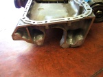 the sump which could subsequently be drilled and tapped. As well as this due to the sump adapter plate on the block the holes in the flanges of the sump that bolt to the gearbox no longer line up with each other. Some people say they have run without these bolts which I dare say is perfectly fine on a very modest build that will be driven gently. However to be safe I decided I wanted these fixings in place. In order to get around this you need to blank the existing
  holes and build up the local area around them with weld. With these mods made and the oil return point drill and tapped I was now finally ready to fit the sump. After a quick test fit to satisfy myself everything was okay I generously applied the Nissan sealant to the sump plate and lowered the sump into place. With the sump finally secured in place I could drill off and tap the gearbox mounting positions as appropriate. As a template I used the dust
 shield from the gearbox and positioned it on the ring dowels in the block then carefully centre punched the hole positions I needed to drill and with a bit of eyeball guidance popped the holes through with a hand drill. I found in a couple of places you then needed to relieve a bit of flat land for a cap head bolt to sit nice and flush. That was it job done!
Inlet assembly and polishing!
It was now time to start putting on ancillary parts of the motor. I was pretty sure I was going to have some playing to do on the exhaust side with the monster turbo so I started with the inlet side to ease myself in! That was a pretty quick easy job and made me feel like a big chunk of progress had been made in quite a short space of time which had been the idea with starting it first.. Keeping me motivated! You will not in the picture I have nice shiny inlet manifold.. I figured the old flaking one just would not cut it so I decided to strip it back flat it down and polish it up. I have to confess I got about 2/3 the way through this very painful job and ended up giving it to a mould polisher to finish up.
 |
 |
 |
You would not believe the amount of work that goes into getting these things shiny! The same was decided or the turbo housing.. I might as well carry the theme of nice and shiny through once I had started! With the turbo housing I invested in a couple more tools and various grits of wet and dry and managed to complete the task myself!
 |
 |
It was worth the pain and blood shed at the end of the day as it sure finished it off nicely.
Exhaust manifold and Turbo Assembly
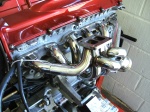
A quick test fit of the exhaust manifold on the block with the turbo showed what I had feared and that was the turbo was going to hit the cam cover! This called for some modification to something! I decided that cutting and shutting the manifold could cause a whole world of pain so instead I opted to  make up a special angle spacer to shim the turbo away from the cover and down a touch to aid with bonnet clearance. I took some measurement and calculated the angle using a 2D CAD model. Then used a 3D scanner to take a template of a pair of exhaust gaskets which I then used to create the profile for my spacer. First of all I mocked up some spacers in MDF to check
 that I had mad the correct calculations and lucky for me the next test fit of the turbo worked out perfectly so I got a metal set done. Next job was to strengthen the manifold to support the giant Holset turbo and also modify the external wastegate pipe to fit the 60mm wastegate I intended to use! This involved me getting a lot of practice using my TIG welder again. The first bit to tackle was cut off the existing wastegate flange and try to determine where the new wastegate would sit. After establishing that and fabricating a suitable section of pipe up then reinforced each of the flange joints with an additional gusset.
 |
 |
 |
With the manifold all set I was now ready to assemble the turbo to the engine and get the wastegate fitted up. Exciting times! It was all coming together and really starting to take shape!

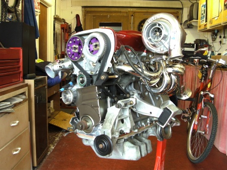
Having bolted the turbo up I now had just two more jobs to do relating to it. Connect up an oil feed and an Oil drain. With the Series 2 RB30 block I had the  oil feed was not functional in the block. The tapped hole was there but it was blind. instead of risk drilling this out I chose to run an oil line from the oil pressure switch position. For this I had to create a special T-block to cater for the different 1/8 BSP and NPT threads of the connecting components. For the oil drain, again with my particular block, the Oil drain position was not tapped in already. There was a boss for where this should be in the casting so I found a tap cheap on Ebay and drilled and tapped a nice big hole in the side of the block to take the
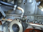 fitting. As this comes out just behind the driveshaft flange I had to weld up a dog leg elbow so the pipe would clear the flange and head off to the turbo in the right direction. There were literally millimetres to spare! Where this was also running close to the manifold to complete the installation I bought some heat reflective tube and covered the rubber portion of the drain pipe in this. Now that completes the turbo installation!
Build Completion
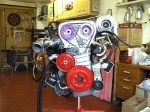
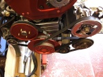
The engine was nearly there. Just a few more bits to throw on auxiliary wise. First of all were the lower belt cover and pullies.
 |
 |
Next was the rest of the auxilary parts. The power steering pump which needed a slight modification to the mounting bracket for it to sit square on the block, the Alternator and the aircon pump along with all the relevant belts and tensioners. You will notice some of these bits got a bit of a shine up on the way!
Well that was it.. The main part of the build was complete and the engine was ready to be fitted back into the engine bay of the GTR!

Engine Fit
So now the ‘tricky’ bit as done it was time for the ‘simple’ bit! With the RB30 Conversion nothing is simple and straight forward. I guess the same applies or any engine conversion project. At least this one uses all the  same auxiliary fittings and wiring. Even if they don’t end up in quite the right place! First of all I had to get the car set up on blocks to raise the front enough that I could crawl underneath to drop the subframe amongst other things. The engine lift only just cleared the front panel but that’s all it needed to do. A few hours later the engine was in the engine bay and bolted to the gearbox. Now don’t be fouled. There were a good few head aches along the way. Mainly the clearance of the back of cylinder head with the brakes pipes due to the increased block height. The increased height also caused the inlet manifold to foul on
 the clutch master cylinder. The Giant turbo generally got in the way. Other than that is was easy! Now I had to fit the rest of the ancillaries around the engine! Radiator and Fan, intercooler piper work. Power steering filler bottle name a few. It was also clear I was going to need to put some some heat reflector on some areas of the engine bay and especially some parts of the wiring harness and pipework that were going to be in line of the downpipe.
After some measuring up and trying to fit various parts of existing pipework from the RB26. I figured the only thing for it was to make it all up as custom! So the list was a little like this:
5) I also required to make up a custom inlet elbow for the turbo to fit the two MAF’s. This was quite a big job and being that I only have a stainless welder I the to manufacture it from stainless steel and not ally.
 |
 |
 |
6) Lastly was the custom downpipe and screamer pipe. Now with all those bits fitted up the engine bay was looking quite shiny from above and below!
 |
 |
 |
 |
 |
 |

 You will have noticed a few other bits of bodywork and paintwork going on through the build which I have not covered. I will cover these on a new page later on.Now the engine was in it was time to fire it up and get some miles on it! I would love to say first turn of the key it barked up but no! Not having too much experience with the Apexi ECU setup didn’t help and no one had mentioned it before but when you reset the ECU it defaults the boost controller kit setting to on. This is an auxiliary piece of kit you can get to run with the ECU that most people dont have! Anyway, with this setting on, the ECU cannot detect a boost controller and prevents the car starting! After a day or so fiddling and asking various questions on forums I found the answer by chance.. First real turn of the key and up she sparked crisp as anything! Very pleasing hearing the burble of a motor I had just put together for the first time! Nerve racking but pleasing all the same! So it really was time to put some miles on it now! The initial 50 miles were done on a dyno so I could get the important initial miles on it and check the base map was safe prior to going for MOT and getting it on the road for some real miles. As I write this I have just covered over 600miles with only some minor issues such as oil, water and air leaks! It is now ready to go for an initial tune. I plan to do this in a couple of stages. Initial tune with standard fuel system in order to be sure any small running niggles are cured and everything works fine so far as fuelling and ignition go before I start upgrading other bits and turning the boost up! Next I will go for a fuel system an MAF upgrade and map again to higher boost. From here I will see where to go. Hopefully that will be project complete and my engine will still be in one piece!
Base Tune 0.8 Bar
Today (25/03/11) I finally got my base tune. After 700miles it was more than ready! As I had some fluffy running issues during the run in period I decided to get a base tune done with the stock pump and MAF’s to make sure it was all running clean prior to swapping MAF’s and more than likely the fuel pump for my future plans. After some minor tweaks richen up the map off boost and load the running issues were all pretty sorted so we went for a couple of power runs starting at 6psi wastegate boost to give the car some initial runs up to 6500rpm. Once happy with that the boost was increased to 0.8bar and some further tweaks were made. At this point the Stock MAF’s were pretty much maxed out so we called it a day but here is what I ended up with so far. The rpm scale is wrong so ignore that. It was revving just short of 6500rpm. The power shown is flywheel power and it equated to 324bhp at the rear wheels I was hoping for a touch more but then I had planned to run it up to 6750rpm initially then I got a bit nervous! I am hoping to dial the power band back a touch to make better use of the cams when I go for the final tune. The 660cc sard injectors were happily running at about 60% duty at the moment. Whether or not I need to put a slightly larger pump in remains to be seen..
Back for a Base tune!
Okay.. So after a minor set back I am back up and running. I found, by chance, that an inlet valve was not seating cleanly and I was loosing compression on no.2. Having had the head back off and re-worked the valve and seat it was back for a base tune! This time I intended to move things along slightly further so went prepared to play with the cam timing and set-up my Q45 MAF’s. This time the results were a little closer to what I was previously hoping for.. Well in fact more than that and on quite a conservative tune. Still running 0.8 bar boost and rev limited to 6750rpm (although not using all of it!) The wheel power increased to 370+bhp. Good boost response and a pretty nice torque curve to go with it!
 And here is what this looks like as an estimated flywheel power and torque too:
 You can see from the AFR curve the fueling still needs some work at either end of the scale.. In fact the idle end has been richened up a touch already as that as pretty lean. But there is plenty of fuel still to be taken out moving up the rev range.As I mentioned I played with the cam timing a bit. I tired about 3 settings on the inlet cam which made little top end power difference but help bring in boost marginally earlier and build a touch more mid range power. I then tried a setting on the Exhaust which again made little top end difference (marginal loss) but bought my spool in a bit earlier still. A couple of degrees again on the inlet then made a big loss! So in the end I compromised with the mid point. I may play a bit more with this when the boost increases and fuelling is closer to the mark.Much to my delight the Q45 MAF’s seem to be pretty good. I have a small low down problem where by it stalls if you let the revs drop off too quick from a hard pull but I think/hope we can adjust that out in the fuelling and playing with the MAF settings a bit more. As it is I have calculated a set of data to run the Q45 MAF’s on the RB26 apexi ECU and globally it seems okay so far. Going to get a few miles driving around this week to make sure!So assuming no more set-backs I need to change the fuel pump to allow for some more boost to be run and I can go back for a final tune!
Final Tune – Sort of!
So, I finally got around to changing my fuel pump. It was not actually half as bad as I thought. I was able to reuse most of the OEM pump frame with a bit or persuasion and it dropped right back into the stock location. It still took a good few hours as I found you need to strip the rear seats to remove the factory fitted stereo amp which sits right over the fuel pump access hatch. You also need to remove 90% of the boot trim and chassis stiffeners! Anyway.. Off to the dyno I went again.. And this time very nervous I must admit! It is the first time I have pushed an engine this far! It was also at the same time quite exciting to see how it would end up!To begin with I decided to leak test the inlet system as I swore I could hear an airleak and idle had been hunting slightly. All turned out fine but I did find out my stock oil breather system setup was leaking through both one way valves! So even though it’s a closed system I expect that won’t be helping anything, especially when it’s on boost! Luckily I was already planning a catch tank to fit! So to start the day’s running my tuner leaned out the map a bit at the top end and altered some of the MAF settings to try and cure the stalling issue. It is better but not perfect yet. More refinement needed! We did a quick run up to warm the car up a bit and check we were starting where we had left off the previous session. Which fortunately we were! So a good start!Anyway, we stepped up the boost to 1.0bar and straight away hit 400bhp at the wheels which was great then 1.1bar and finally 1.2bar. At 1.1bar it jumped up to 425bhp and we then started to notice a couple of strange issues. Firstly the AFR’s had gone rich with no Map change! And secondly the boost was dropping off at the top end. The latter boost issue was most likely put down to a weak wastegate spring not holding the exhaust pressure. So hopefully I can simply pre-tension it and rectify that or get a new spring. The fuel issue is a little more strange and needs further investigation. However from the pattern seen on the dyno it may be that the air inlet temp had risen sufficiently to cause the Apexi ECU to start applying a fuel correction which globally richens the fuel mix. However this theory needs testing and also I need to get an inline pressure gauge to be sure the pump is not behaving strangely. Or indeed another sensor is dicky! Anyhow the end results were as follows: Here the upper graph shows the boost pressure and you can see it tailing off as the rpm increases dropping back to about 1.1 bar.
 This graph shows wheel power and torque. 437bhp and 410ftlbs! Please note the rpm scale on the graphs is a little out as it goes up. The rpm cut was 6750 but a you can see it was peaking just below that. We did take it up higher but there seemed no point as currently the cams are set to maximise boost response and low down power. Finally estimated flywheel power:
 518Bhp @ 6500rpm. Not too bad I guess?! You will notice on this graph as with the previous one, it is two runs overlaid and the AFR curve at the bottom is a step down on one run from the next. This is the issue I need to look into. It seems quite likely it is some kind of ecu induced scaling as the whole curve has shifted by what looks like a pretty even amount?! We will see.So, the result were a little under what I was hoping. Still if I can resolve the fueling and boost issue there is a little more to come so I should get close to my goal. Will have to wait until next time now!
Final Tune – Take2!
Okay guy’s so I went back to the dyno again! I had no time to get a new wastegate spring since the last trip so I tried to put some pre-load on the spring to see if that would work. I had programmed a new MAF table for the Q45’s and raised the airtemp correction value and also increased the warm water correction temp as the car never seems to get over 70deg and this seemed to solve the random problem of the car getting richer every run! My tuner then trimmed up the fuel some more (still running very safe) and did a few runs but still the boost was dropping off as the revs increased. In the end in a effort to try and get a representative run my tuner held half throttle to build the rpm up to around 5000rpm and then hit the throttle to try and get the boost to hold out for redline. Still no joy! Anyway. In the end I came away with 451bhp at the rear wheels. with the boost dropping off below 1.1bar! So would estimate at least another 10-15bhp if I could hold 1.2bar boost on the dyno. Annoying because it holds boost on the road fine!Some more pretty graphs below! I might investigate the boost drop off further and get some other feedback on my dyno plots. If its worth going back again at a later date I may!

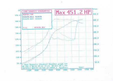


The whacky graph is from where we tried slamming the throttle at the end of the run!
Last Dyno Attempt
Okay.. So after the last efforts and the boost drop of seeming to be holding back from making any more power I thought it was time for a couple of little modifications and then maybe another go! So the only real options I had with the car going from feedback I was getting was the wastegate was not holding pressure because the spring was too soft and maybe the exhaust system had to much back pressure. Or because the turbo was too small. Well I was pretty confident the turbo was not too small! So I opted to free up some flow in the exhaust and change the wastegate spring for one closer to the 1.2 bar I was trying to hold. Wastegate was easy enough.. I knew the spring was only about 7psi.. which is pretty soft! So I pulled out one of the meaty springs it came with and fitted that.. That ended up giving me about 12psi on the wastegate which was much better. Next was the exhaust that was a little more tricky.. I crawled under the car and the nice HKS cat back system had a dirty great centre box dog legged into the system. Sure it won’t be helping and the car was very quiet as it was which would also imply a bit of restriction could be happening. So I had a look around the forums to see if I could finding anything going second-hand with no luck. It could only mean one thing. Time to get my Tig welder out again! So I had a measure up and ordered a section of stainless pipe to replace the centre box with.I have to say the job was complete cow to do with the car on a small lift and a jack! I had to try and tack it all in place with it all in situe.. Not the easiest of jobs with a tig welder whilst lying on you back under a car! I must say just for the added growl it gives the car it was worth the pain! It sounds glorious!
 |
 |
 |
There was only one other thought I had on the boost drop off and that was the cam timing. As it was set for low down power and spool up it could be restricting the flow at the top end? So I also decided to whip off the timing belt cover ready to do some tweaks! It was time to get back on the dyno and see what the results were.To start with the initial run showed the car to be running hugely rich and making less power than before! A bit odd. I had had a road tuning session in-between though which could have resulted in this as well.. On top of that I was suffering badly with wheel spin all the way through the rpm range! After basically a full re-map to get the AFR’s looking sensible again we tried some runs. Still suffering with wheel spin but making the power as before but with slightly less boost! Sadly I had not sorted the boost drop off though. Still a mystery to me! I tried to tweak the inlet a couple of degrees advance to see if this would help but no joy. On a plus it picked up some more power throughout the range! In the end the results were much the same as before but now the boost had been set marginally lower and I had gained a good bit of torque and some more low end power. All in all I could complain.. Just a shame about the boost drop off. It holds it fine on the road a far as I can see so I would guess in reality it is making a few horsepower more than captured on the dyno.

 Not the tidiest of graphs due to the wheel spin.. But as you can see peak power at the wheels comes in at 451.9bhp with well over 300 of that at 4000rpm! That gives and estimated flywheel power of 535.5bhp. Peak torque is up on last time to about 430ftlbs. Would love to see what it would pull if the boost held!I will have to try and restrain myself from tinkering now so I can enjoy using the car but we will see!I would like to thank Geff at Reworx for a great job of tuning the car and also Dan at Auto Sport North for some very helpful advice along the way. You can find contact details and more info for both these guys in my Recommended section.


April 29, 2010 at 12:04 am
Awesome! Love your work!
May 31, 2010 at 9:49 pm
priming oil system procedure is available via email…please contact.
October 24, 2010 at 9:24 pm
awesome mate enjoyed reading that
May 2, 2013 at 2:59 am
Good work mate.hope ya can sort ur boost issue.good read.